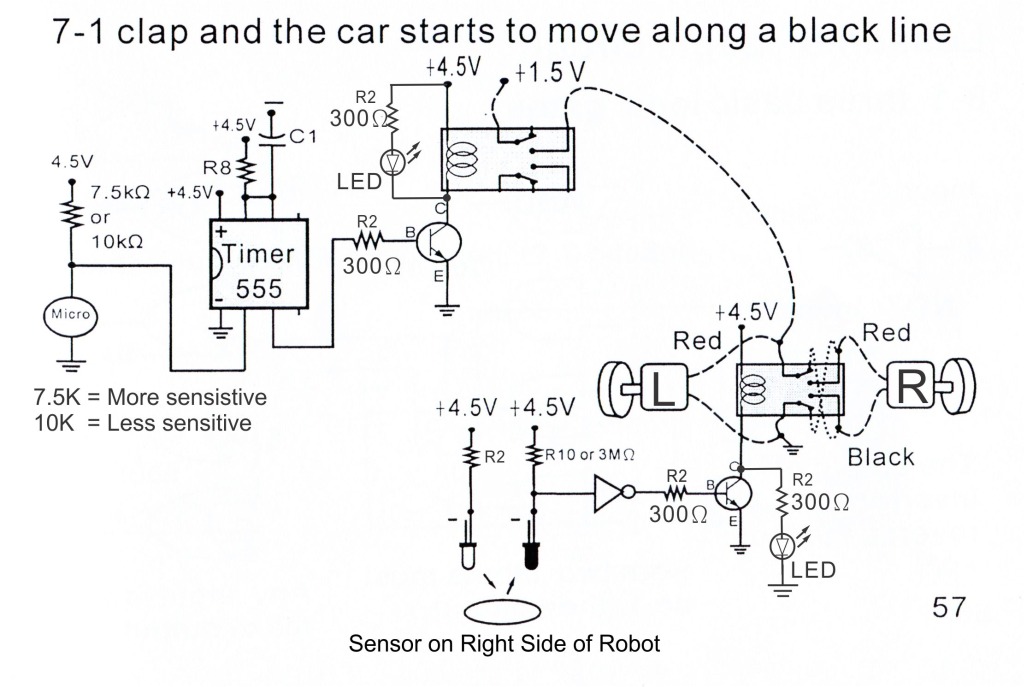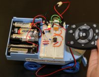
This project allows you to steer the Letry robot with any normal TV/DVD player IR remote. The robot drives forward in a straight line until it receives a signal from the IR remote, as soon as it does it will start turning for a set time. To adjust how long the turn lasts you can experiment with the value of R3 and C1.
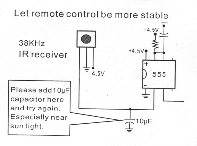
The C1 capacitor can be changed from 100uf to 10uf, see what happens! Why do you think this is?
Almost any common IR remote control from your TV or DVD player will work, as long as it sends out its IR pulses at 38Khz it will work, 38khz is the most commonly used frequency.
Letry IR schematic Update
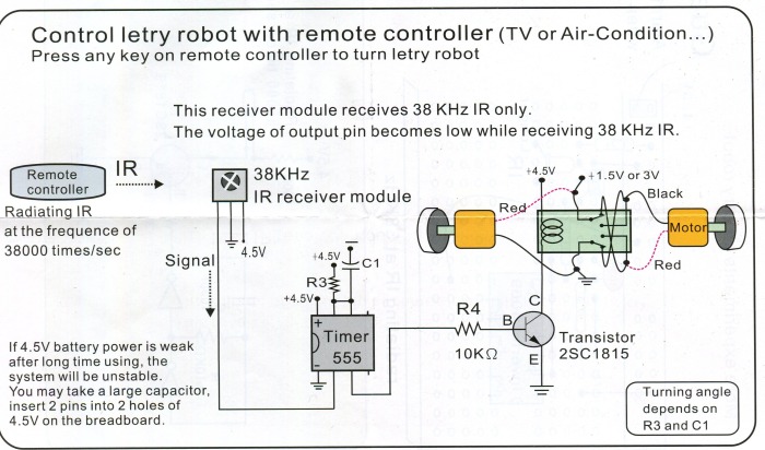
Letry IR Receiver Schematic
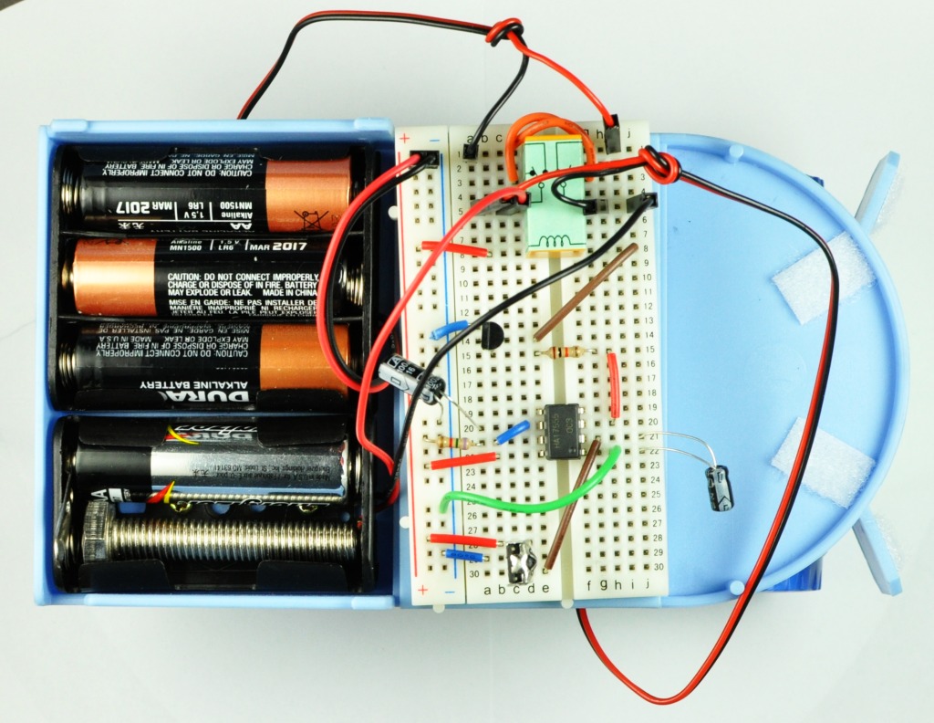
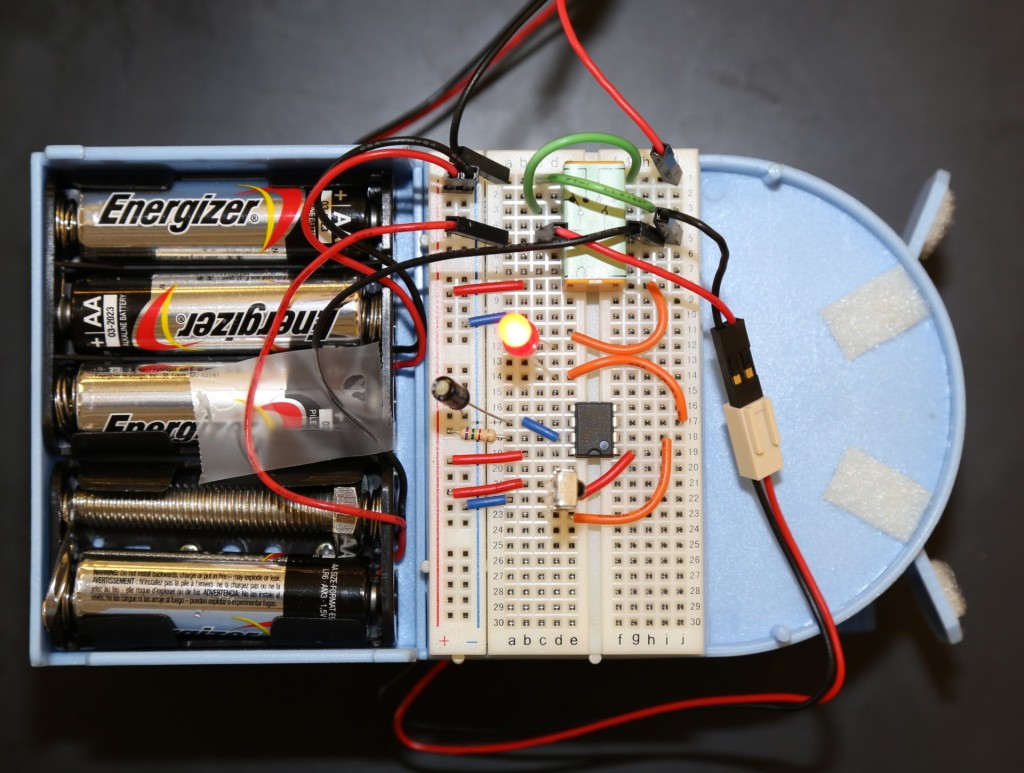
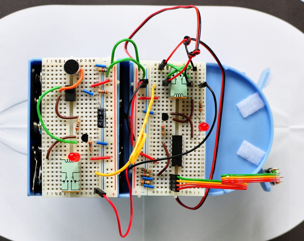
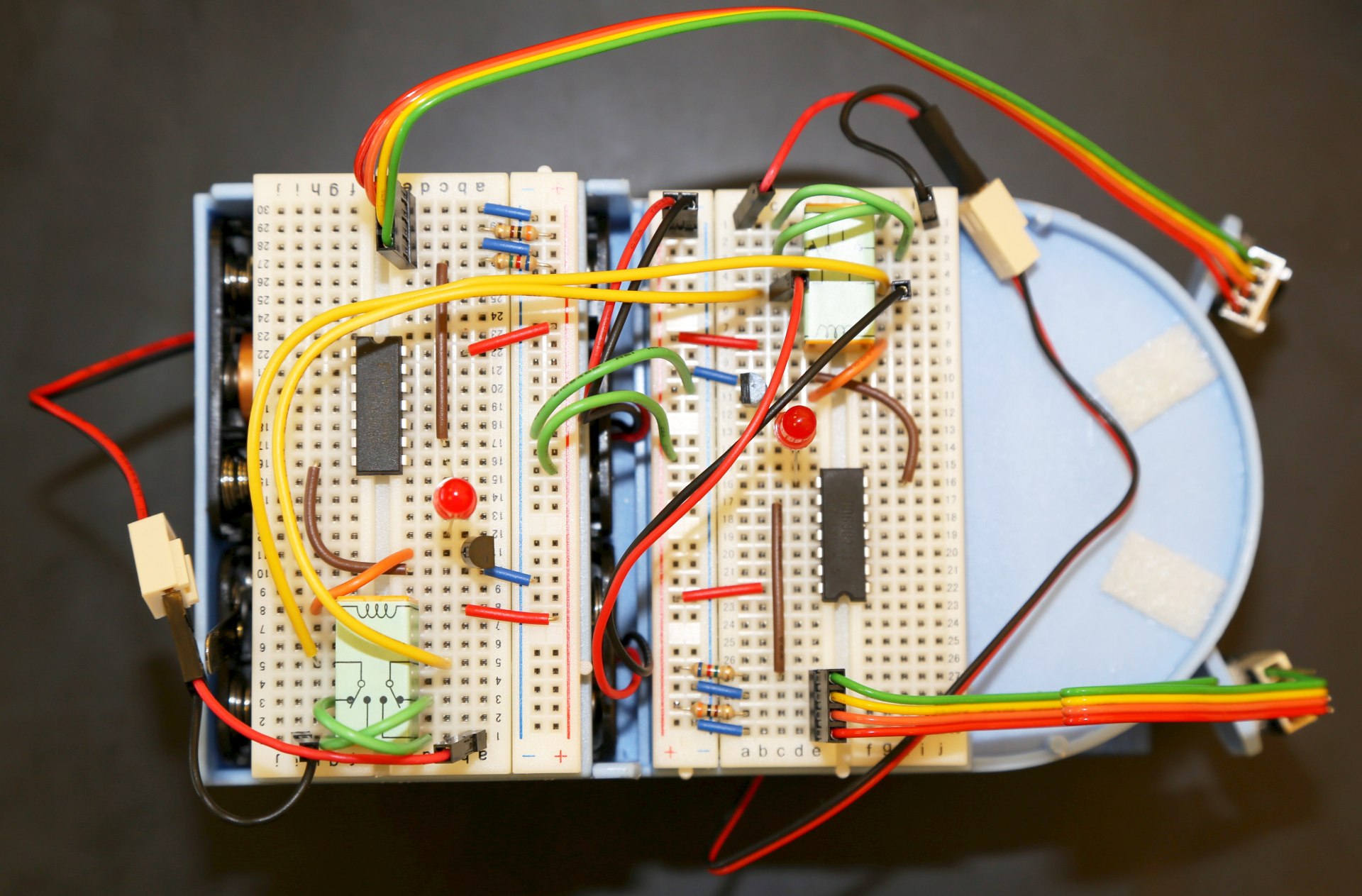
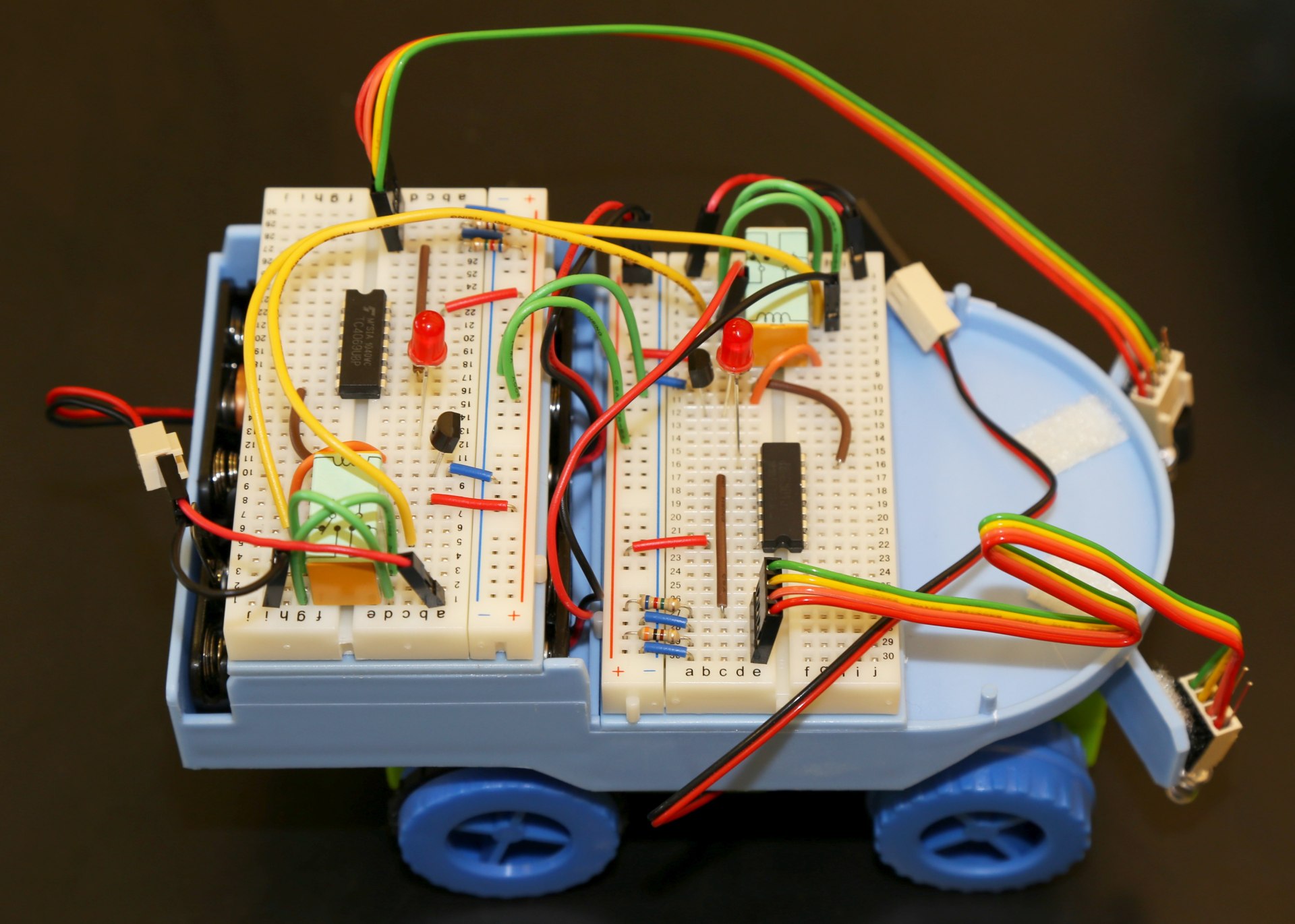
IR Receiver Layout
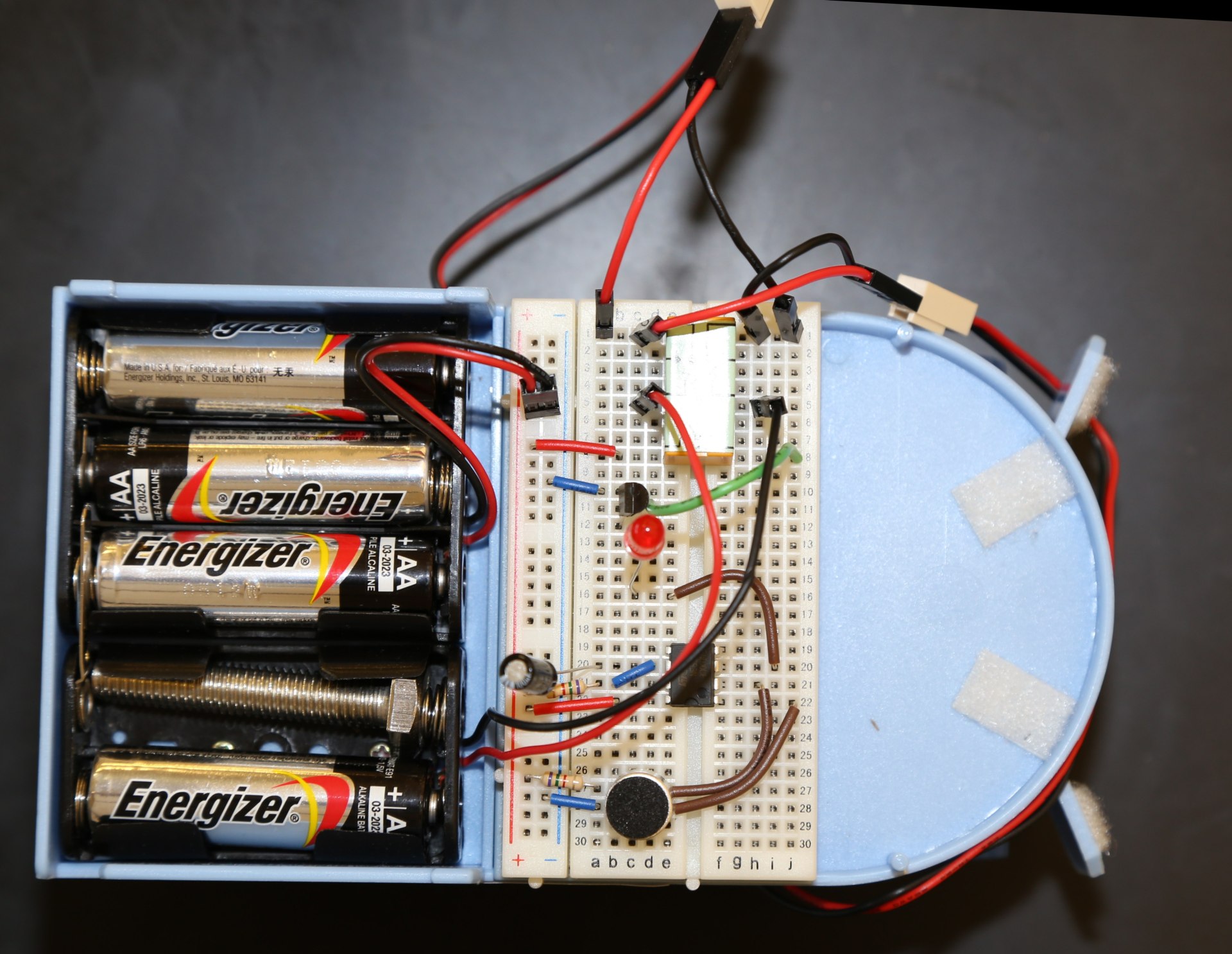
NOTE: The following two images may look like entirely different circuits to you! they are not! but do have some changes in the wire placement from the previous image, either one will work.
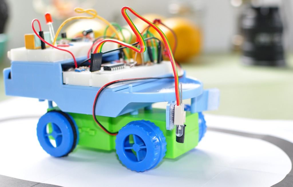
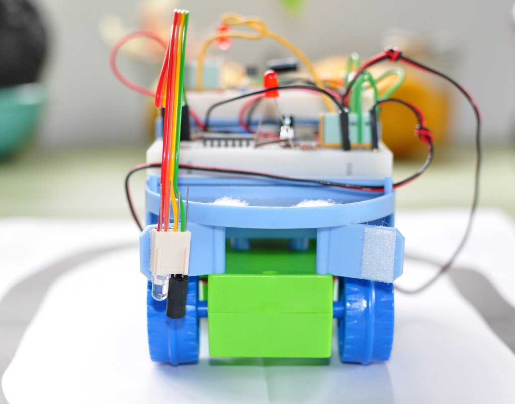
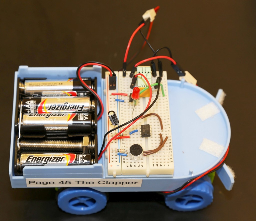
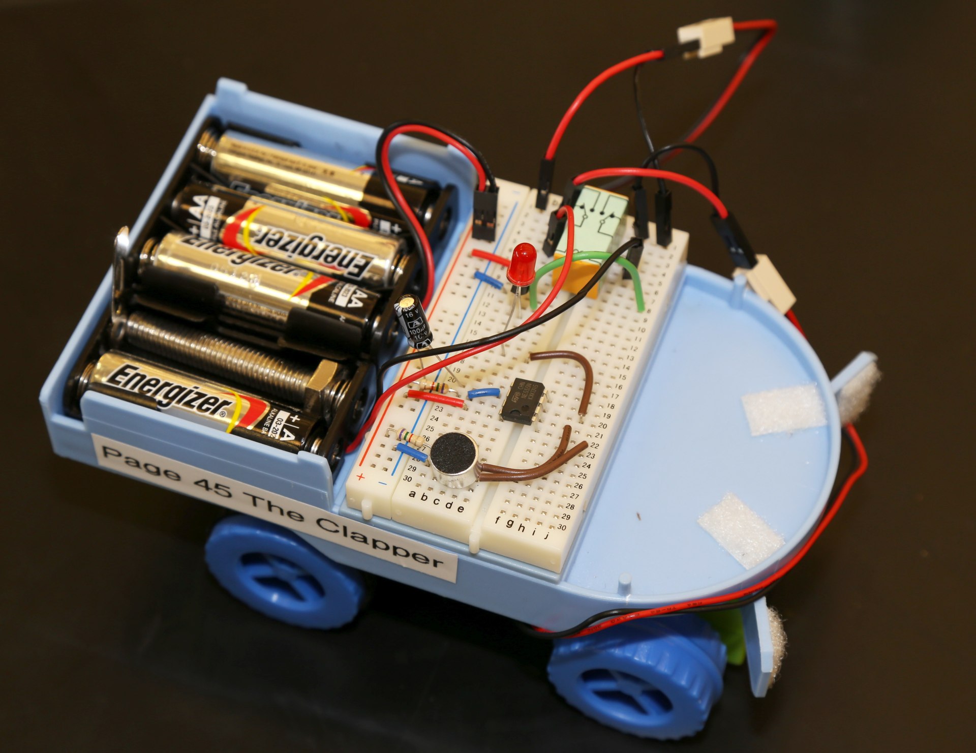
The following two images show how you can use a red LED (Watch polarity!) to provide visual indication when the microphone input is triggered.
the transistor is behind the red LED in this image, you can see its placement in the last image.