Posted on

Free Shipping On All Orders Over $100!

As we have developed more products free shipping has finally become a viable option!

Any order to the USA above $100 total will ship free via USPS Priority!

The attached picture is of a new Raspberry Pi compatible pin out diagram we will be giving away with every order as soon as they arrive from manufacturing! (expected here by 10/20/2018)


Posted on

Easybotics Brushbots in Kenya!

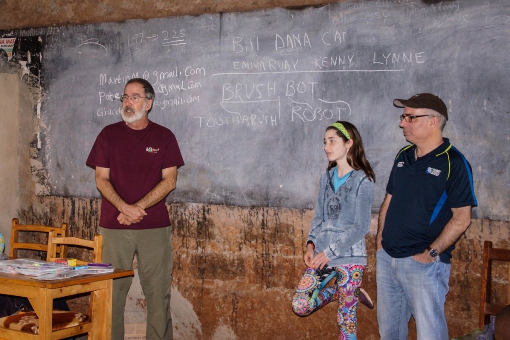
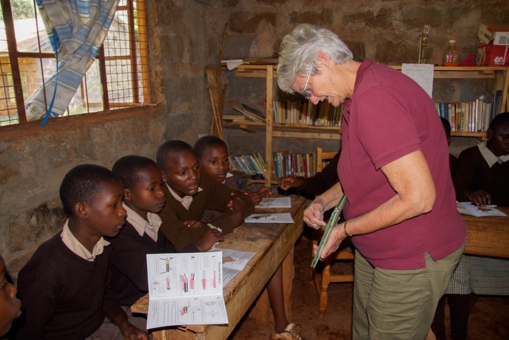
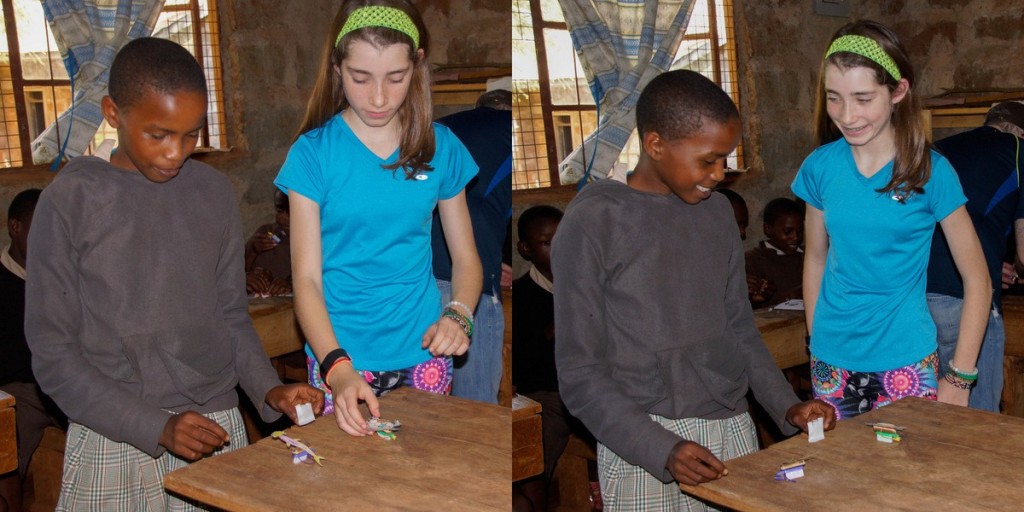
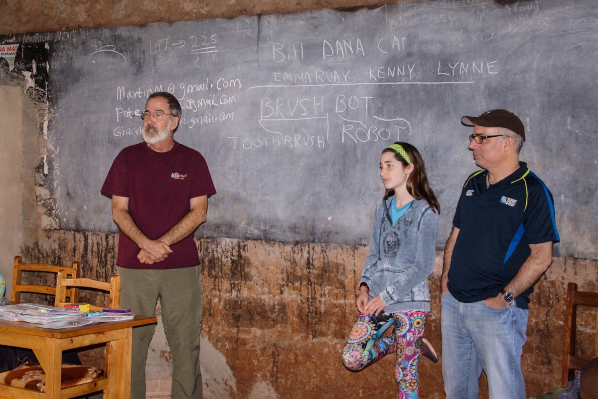
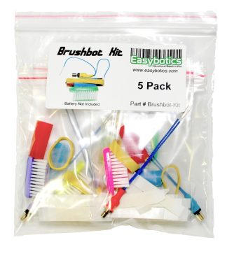
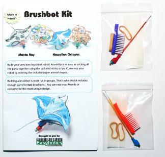
In June of 2015, travelers took 25 Easybotics’ Brushbot kits (2 Brushbots in each kit) to a small rural primary school in Kenya to share the excitement of science and engineering with the 7th grade students.  Bill Rathfon and Dana Reed, both engineers and supporters of the organization “Iruri Primary School – Sharing a Vision”, were visiting the school while on safari, and wanted to bring along a hands-on project for some of the students at the school.  Graham Seiki, Tech Coordinator at an elementary school in Lahaina, Maui, HI, and advisor to the Lahainaluna High School robotics program, suggested the brushbots from Easybotics.

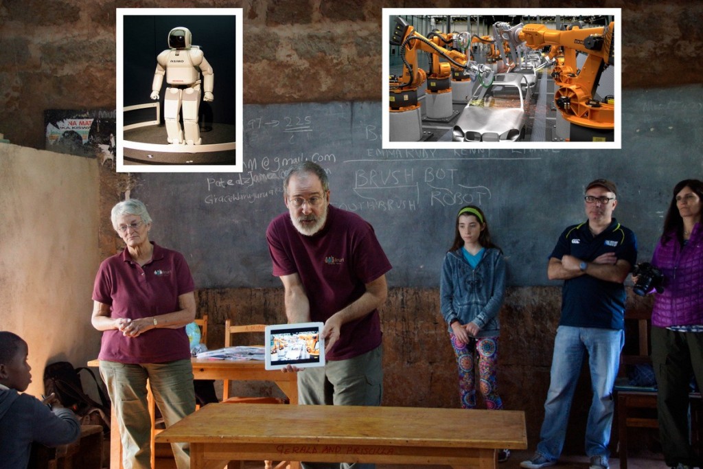
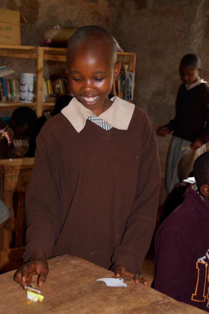
The venture was a huge success.  The kits are an excellent activity that tie science concepts, engineering concepts, and even some art together to make a great teaching springboard.  The students at the school have a very rigorous science curriculum, but do not have the resources for much hands-on experience such as labs.

Iruri Primary School – Sharing a Vision would like to thank Easybotics for their support of this project that reached out half way around the world to promote science, engineering and goodwill.  To find out more about what is happening at the school, visit www.irurikurota.org.

2-brushbots-115


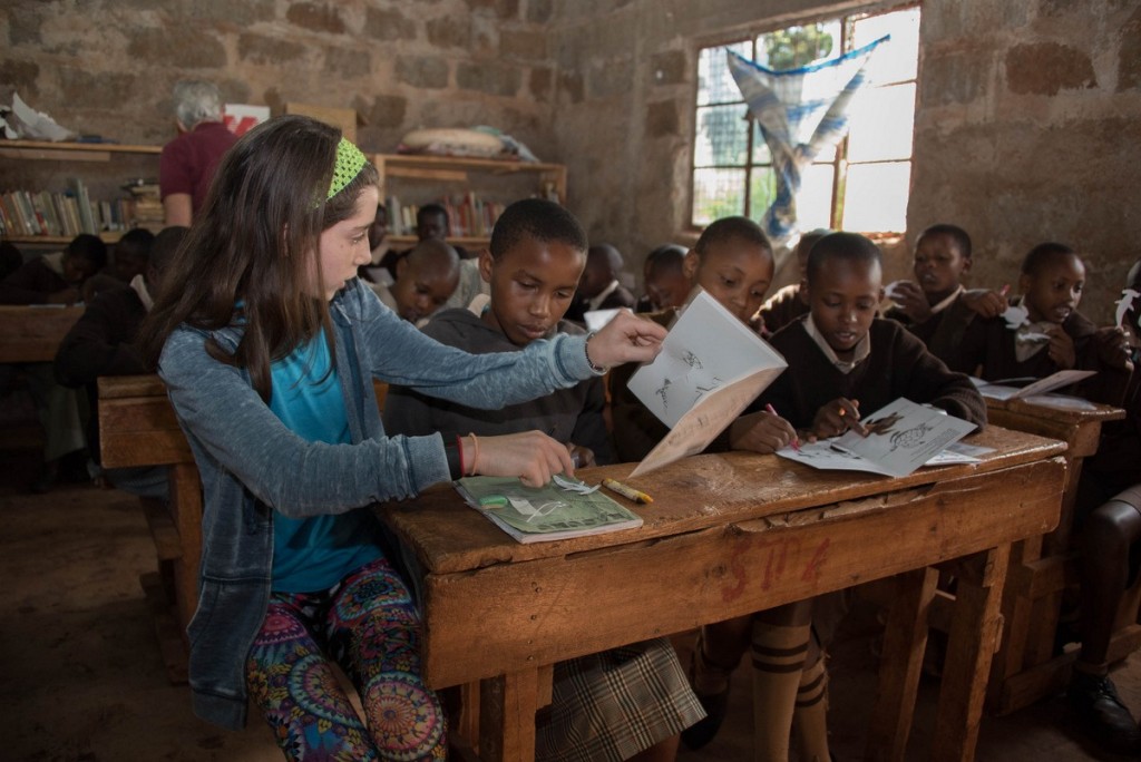
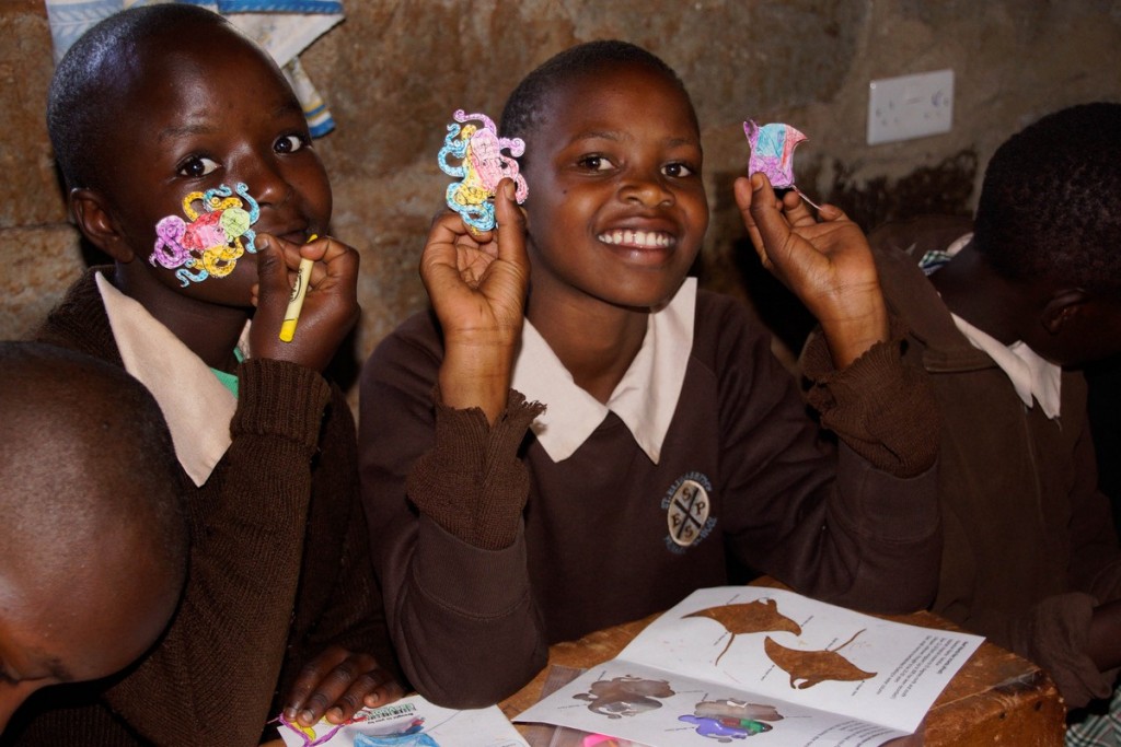
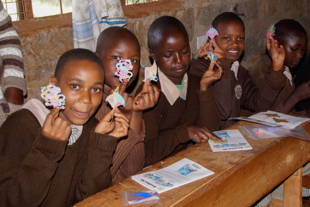
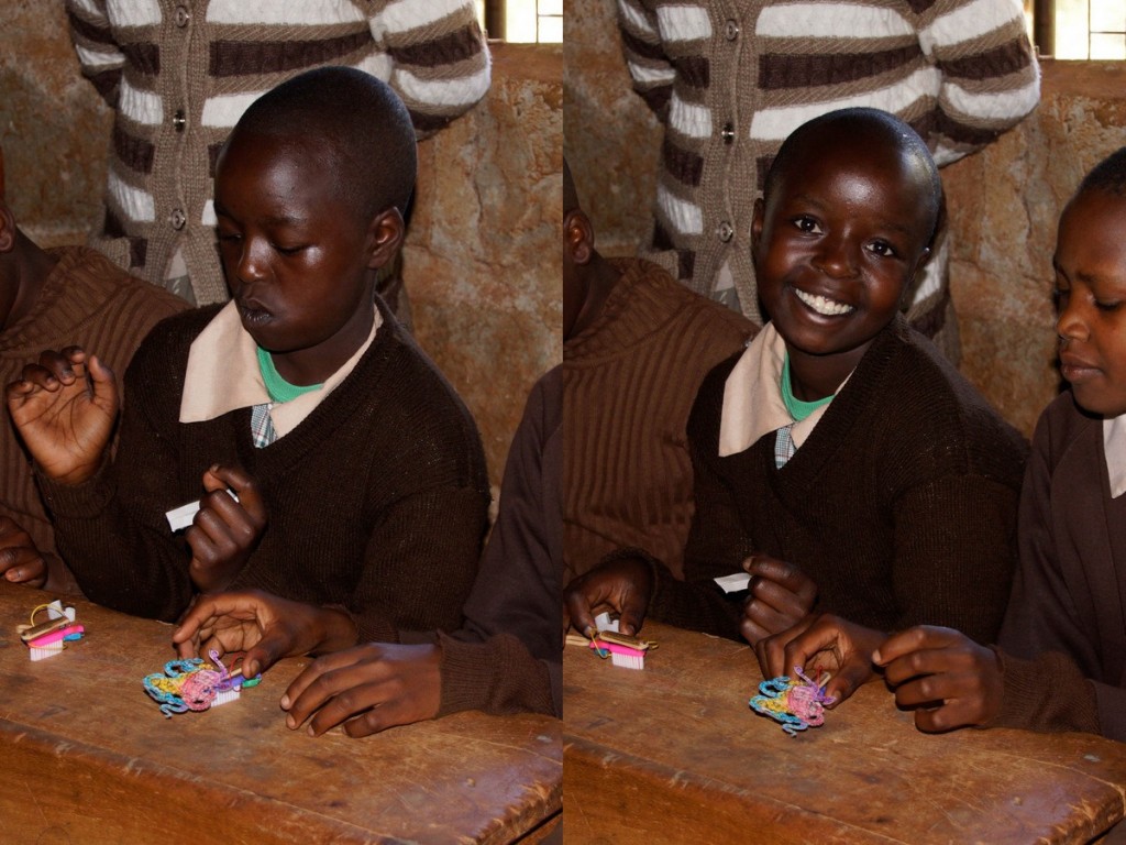
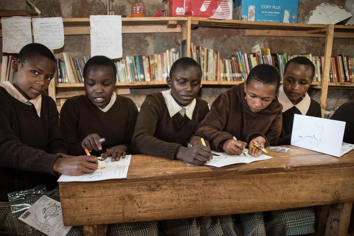
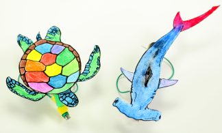
These students are coloring the Brushbot decorations (shark, sea turtle, octopus or manta ray) in preparation for assembly.

3-brushbots-122

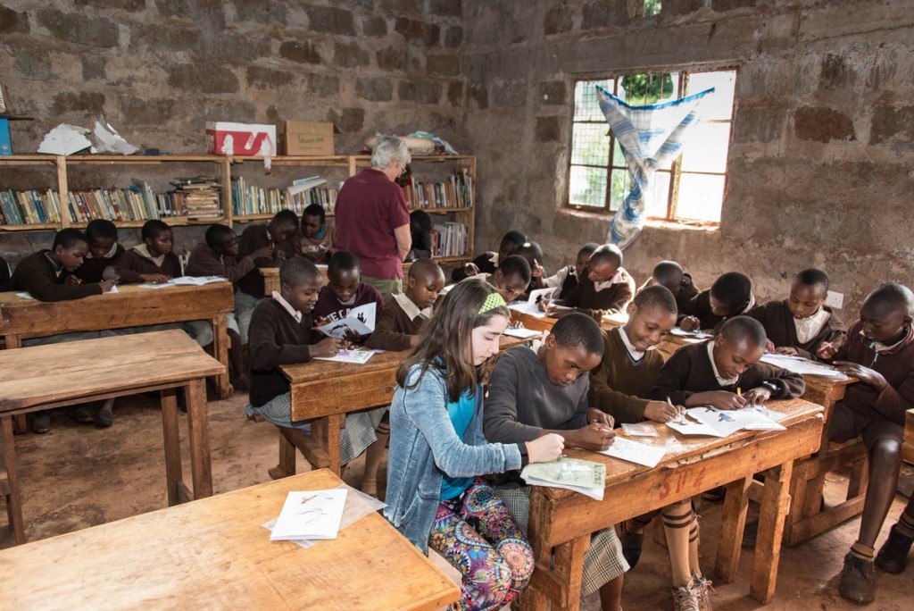
Also involved was a 12 year old girl who was on safari with her parents.  She had just done a programmable robotics project at school and was very excited to help.

01-from-cat-8056 1-brushbots-111 02-from-cat-8060-Edit 03-from-cat-8074 04-from-cat-8098 05-from-cat-8100 06-from-cat-8103 07-from-cat-8111 08--testing-brushbots 09-success 10-from-cat-8129

Posted on Leave a comment

Letry and Arduino – Getting Started

If you do not already have the Arduino IDE installed on your computer please go to the download page here: http://arduino.cc/en/Main/Software

Once you have the Arduino program open go to Tools > Board > Arduino Uno. This sets the board target as the Arduino Uno, this board uses the exact same IC chip as the one included with the letry kits (ATMEGA328) it just does not have a PCB(printed circuit board) attached to it.

selectingBoard

Now go to File > Examples > 03.Analog > AnalogInput and open the file.

analogInput

The “AnalogInput” program you have just loaded contains the following code:

int sensorPin = A0;    // select the input pin for the potentiometer
int ledPin = 13;      // select the pin for the LED
int sensorValue = 0;  // variable to store the value coming from the sensor

void setup() {
  // declare the ledPin as an OUTPUT:
  pinMode(ledPin, OUTPUT);
}

void loop() {
  // read the value from the sensor:
  sensorValue = analogRead(sensorPin);
  // turn the ledPin on
  digitalWrite(ledPin, HIGH);
  // stop the program for <sensorValue> milliseconds:
  delay(sensorValue);
  // turn the ledPin off:
  digitalWrite(ledPin, LOW);
  // stop the program for for <sensorValue> milliseconds:
  delay(sensorValue);
}

Now you have completed the basic software setup side of things 🙂 what remains is the fun task of wiring up the hardware!

Warning: when inserting and removing large ICs like the ATMEGA328 from the breadboard, keep both sides parallel to the breadboard, sometimes it helps to use a small flat head screw driver to pry up each side evenly when removing. If you pull up only one side at an angle you will bend the pins, potentially breaking them off.

analoginLED


Posted on 1 Comment

4x Faster Webserver!

We have just switched hosting providers to a much faster server! pages should load much quicker now.. Please let us know if you notice any problems on the new site or just things you would like to see added. 🙂

Because web-servers aren’t very photogenic we have included a picture of a one cubic inch robot – the PCB itself is 23mm x 23mm.


CCBot

Posted on Leave a comment

Letry – IR Remote Control

This project allows you to steer the Letry robot with any normal TV/DVD player IR remote. The robot drives forward in a straight line until it receives a signal from the IR remote, as soon as it does it will start turning for a set time. To adjust how long the turn lasts you can experiment with the value of R3 and C1.

The C1 capacitor can be changed from 100uf to 10uf, see what happens! Why do you think this is?

Almost any common IR remote control from your TV or DVD player will work, as long as it sends out its IR pulses at 38Khz it will work, 38khz is the most commonly used frequency.

Letry IR schematic Update
Letry IR Receiver Schematic
IR Receiver Layout
IR Receiver Layout


NOTE: The following two images may look like entirely different circuits to you! they are not! but do have some changes in the wire placement from the previous image, either one will work.

The following two images show how you can use a red LED (Watch polarity!) to provide visual indication when the microphone input is triggered.
the transistor is behind the red LED in this image, you can see its placement in the last image.

Layout3LLayout2L


Posted on Leave a comment

Dual Obstacle Avoidance – Page 41

This circuit allows the robot to respond to two IR reflective sensors at the same time, allowing it to avoid obstacles on either the left or right sides, or (once the motor leads are switched) to track a black line as provided in the kit.

Red LEDs have been added to help you debug sensor placement. With the motor switch in the OFF position, watch the red LEDs and move the robot from left to right across the provided black line, if everything is working properly the light should go on and off completely as the black line is passed.

Note: The two breadboards shown below are identical, the front one goes to the right motor, the back one to the left motor. If you cannot see how a component is placed on one breadboard, just check the other one as they are the same.

If the IR reflective sensors are not working correctly here are some things to try:
Bend the clear IR emitter so that it faces perfectly forward.
Move the sensors closer or futher from the ground – it is possible to go too close! about 3/4″ (19mm) is a good distance from the ground table surface.


Line3L Line1L Line2L

Posted on Leave a comment

Current Projects

The latest bipedal robot is almost ready! Here you can see the last prototype with the 8×8 LED matrix face, and the latest one with an 128×64 OLED display 🙂 the screen can display custom graphics or text in real time. One great use of the display is in debugging your code, you can print variables directly to the display, no serial terminal needed.


IMG_8726

IMG_8694-001